


UAA Model Bridge Strength Competition
Teacher Deadline Update
Teachers who wish to receive classroom support for the UAA Model Bridge Strength Competition should register by January 12th, 2026. Additional information and a link to the request form are available below.
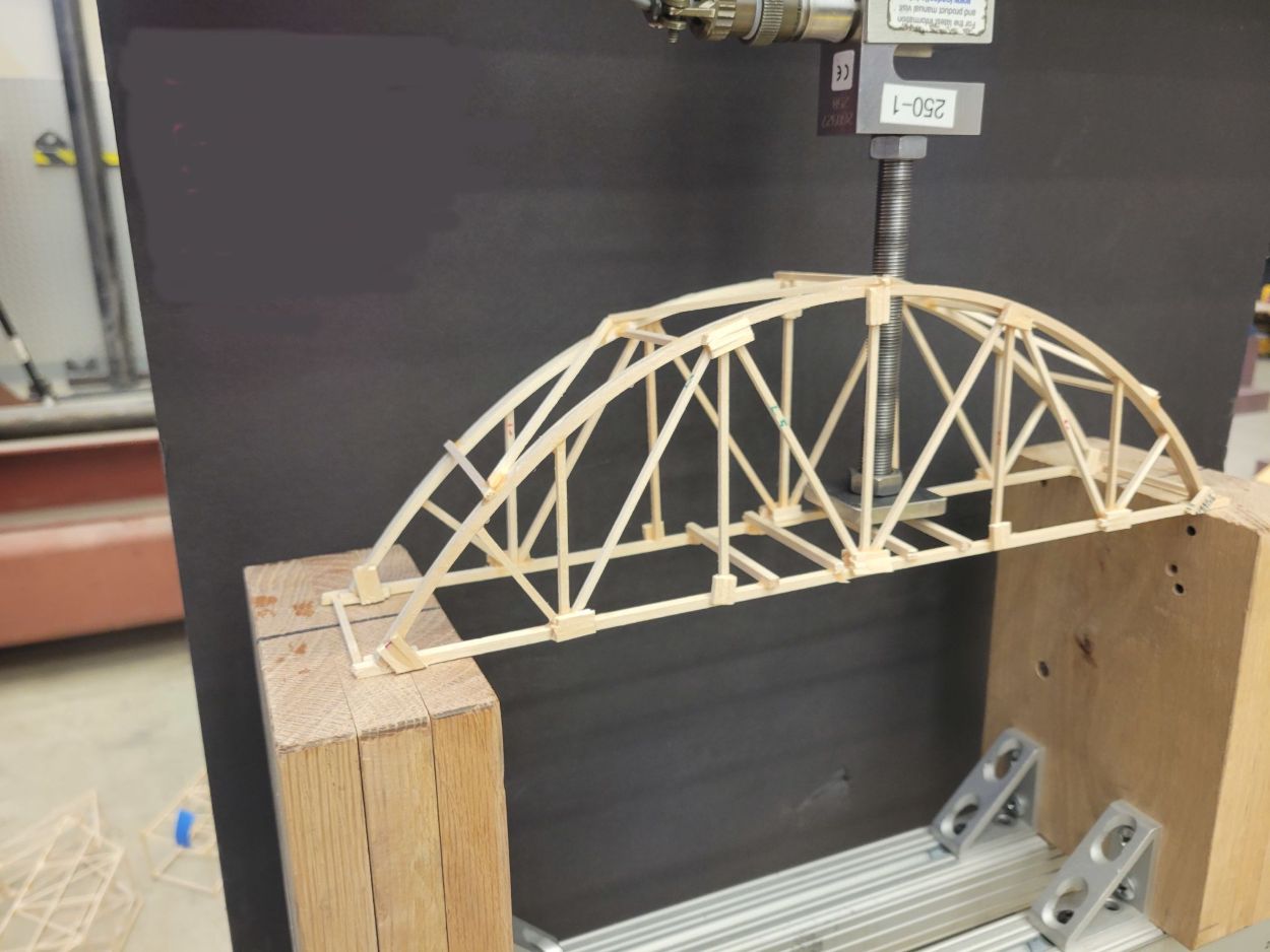
Image of bridge for bridge strength competition.
General Information
For Students and Families
The UAA Model Bridge Strength Competition is an opportunity for middle and high school students to compete against each other to build the strongest bridge with the greatest efficiency. This competition is part of Anchorage Engineers Week, and it gives students the chance to put their engineering, creativity, design, and construction skills to the test. Participants will design and build a bridge at home or in class, and then Dr. Scott Hamel and his college students in the UAA chapter of the American Society of Civil Engineers will test the bridges' strength... by crushing them! This is a fun and engaging way for students to explore the principles of structural engineering.
- Who: Current middle and high school students
- Where: UAA Engineering & Industry Building (2900 Spirit Drive)
- When: February 21, 2026 (Complete your bridge build before this date.)
- How Much: Free! (Materials not included for individuals.)
How Can I Participate as an Individual?
If you or your child are interested in participating in the competition as an individual, then we have a few requirements and recommendations.
- Read carefully through the official rules on this webpage and reach out to us if you are confused. If a bridge is incorrectly sized, then it may not fit into our "crushing machine" and it will be disqualified.
- Seek primers on structural engineering basics to gain a solid foundation for your bridge design and construction. For example, this unit on bridges from TeachEngineering.com is a good introduction to core concepts.
- Purchase materials for your bridge early. We recommend procuring the materials through local hobby shops or online, but you should be aware of available supply and shipping times.
- Before starting construction, check out the "Tips and Suggestions" at the bottom of this webpage. It will help you to avoid common mistakes that will negatively affect your bridge's strength.
- Complete your bridge prior to the date of the competition. And be aware that glue connections become harder the longer they have to cure. We recommend finalizing your construction at least 24 hours before we crush it.
- Arrive during the Engineers Week Student Competitions on Saturday, February 21 (exact time TBD) and go to the Student Innovation Center in Room 108. Alert our staff, then wait for your turn for destruction!
For Teachers
If you are a teacher who is interested in using the UAA Model Bridge Strength Competition as a tool for teaching students about structural engineering, the engineering design process, or the real-world applications of physics and math concepts, then the UAA College of Engineering is willing to provide the following to support you:
- All materials necessary to run the activity, including wood, glue, tools, etc.
- A lesson plan for running the activity in conjunction with your curriculum. In total, the activity will take approximately 3 to 5 instructional hours.
- Classroom support from an engineering expert, who will be available to explain the principles, go over the rules, share advice, and support the activity from A to Z.
This activity is a perfect way to supplement your science, math, or engineering class curriculum with a fun, hands-on activity that is grounded in real world applications and career pathways. And our goal is to make it as easy as possible to integrate it into your class.
How Can My Class Participate?
The process for signing up your class and running the activity is simple.
- Fill out our request form no later than January 12th.
- Coordinate materials and classroom support needs with the College of Engineering in mid-January.
- Complete the classroom activity over approximately 3 to 5 instructional hours before February 21st.
- Have students participate in the competition on February 21, 2026.
We understand that this may not work for every teacher's curricular schedule. When possible, we are willing to work with you to develop alternative plans for offering this activity to your class. If you have any questions or wish to discuss this in more detail, please reach out to Dr. Scott Hamel at sehamel@alaska.edu.
Official Rules
Download the official rules to print at home or share in your classroom.
Introduction
These rules are a modification of the rules for the International Bridge Building Contest.
Objective
Design and build a bridge that will support the greatest weight (maximum applied load) while meeting all the required specifications.
Categories
The contest is open to students grades 2-12. Participants may enter as individuals, pairs, or small groups. If a school competition has been held, winners may enter to represent a school or organization. Teachers or group leaders who wish to use the contest as a class activity may request a classroom visit and/or mentorship from a Structural Engineer. Email Scott Hamel at sehamel@alaska.edu.
Specifications
- Materials:
- You may use any commercially available Basswood that does not exceed 3.5mm (1/8 inch) in any orthogonal cross-sectional dimension. There is no limit on the length of the pieces. Note: only 3/32x3/32 members are allowed for the International Contest.
- Glue is to be any commercially available wood glue or super glue. Hardened glue by itself may not be used as a structural member. Non-wood fasteners, such as screws, may not be used.
- The bridge may not be stained, painted or completely coated in any fashion. Decorative designs may be applied to the members provided they do not prevent judges from identifying the wood.
- Construction:
- Mass: Bridges should be at or below 25 grams. Bridges more than 25 grams will be penalized by multiplying the max applied load by a reduction factor equal to: [(25 grams / actual mass)2].
- Length: The Bridge (Figure 1) must span (S) a 305 mm (12.0 inches) canyon opening. The bridge must sit on at least 25mm (1.0 inch) at each end, which means the overall length (L) must be at least 355mm (14.0 inches). The overall length (L) of the bridge cannot exceed 406 mm (16.0 inches). Bridges that are too short will not be tested.
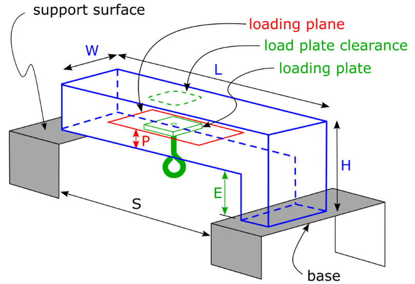 Figure 1. Bridge Schematic (not to scale)
-
- Width: The bridge must be no wider (W) than 80 mm (3.2 inches). The width is measured at the loading surface. There is no minimum width. Bridges which do not meet these criteria will be penalized.
- Height: The height of the bridge above the support surface (H) may be no more than 152 mm (6.0 inches). There is no minimum height. The bridge may not extend below the support surface.
- Load Point: The bridge must provide a horizontal loading plane (P) that is between 5 mm (1/4 inch) and 152 mm (6.0 inch) above the support surface. The support must accommodate one loading locations at the center of the bridge. Any portion of the structure above the loading plane must provide clearance for the "loading plate" and for the rod below the plate (Figure 2).

Figure 2. Loading Plate Detail
-
- Support: The bridge shall be supported by the bearing (sitting) on the horizontal support surfaces at each end. There will be a lower and an upper support surface, separated in elevation (E) by 12mm (0.50 inch). The vertical face of the canyon may not be used to provide support for the bridge, nor may supports sit in the water on the surface below the span (bottom of the canyon). Bridges that touch the sidewalls or bottom of the canyon will be disqualified.
In summary:
-
- Maximum Mass: 25 grams
- Opening Span (S): 305mm (12.0 inches)
- Minimum Length (L): 355mm (14.0 inches)
- Maximum Length (L): 406mm (16.0 inches)
- Maximum Width (W): 80mm (3.2 inches)
- Maximum Height (H): 152mm (6.0 inches)
- Support Elevation Offset (E): 12mm (0.50 inches)
- Loading
- Loading Plate: Load will be applied by means of a 40 mm (1.60 inch) square plate (Figure 2). The plate has a thickness (t) between 6 mm and 8 mm (approximately 1/4 inch). The loading plate will be placed from above on a 3/8 inch threaded rod with two sides parallel to the longitudinal axis of the bridge. Force will be applied to the rod.
- End of Loading: The largest supported load throughout the testing will be taken as the maximum applied load. Loading is stopped if the bridge breaks (i.e., an obvious peak is reached in the applied load measurement), or the bridge touches the sides of the load support or bottom of the load frame.
Tips and Suggestions
Triangles! The most efficient bridge designs use trusses, which have “holes” that are triangular. Common trusses are the Warren Truss, the Pratt Truss, and the Howe Truss.
To help you meet the weight limit, the approximate weights of some pieces are shown. Balsa wood is not used because it has a huge variation of density and strength.
High quality wood glue, such as Titebond II provides a strong and durable joint, but takes up to 24 hours to cure. A fairly new product: Titebond Quick & Thick provides similar strength but dries much faster (though full cure is still 24 hours). Fast-dry (3 second) superglues do NOT form strong bonds, because they only bond to the surface. Slower (30 seconds) superglues can be as strong as wood glue. Polyurethane glue, such as Gorilla Glue, likely has similar strengths (though we have not tested it) and expands to fill cracks, however it requires moisture to cure, so surfaces should be wetted.
|
Type |
Size (inches) |
Approximate Weight (g) |
|
Basswood |
3/32 x 3/32 x 24 |
1.6 |
|
Basswood |
1/8 x 1/8 x 24 |
3.0 |